Button Pad Controller SPI Sparkfun – Obsolete
$ 34,95 $ 20,97
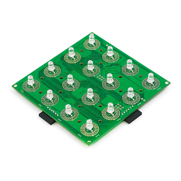
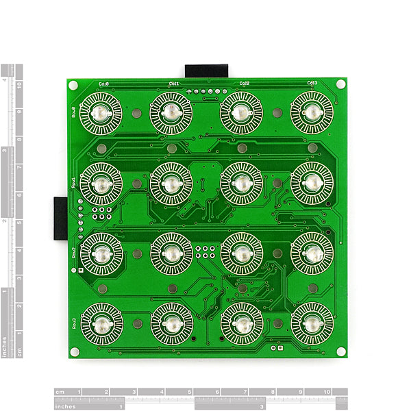
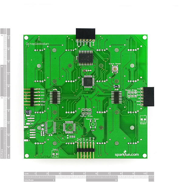
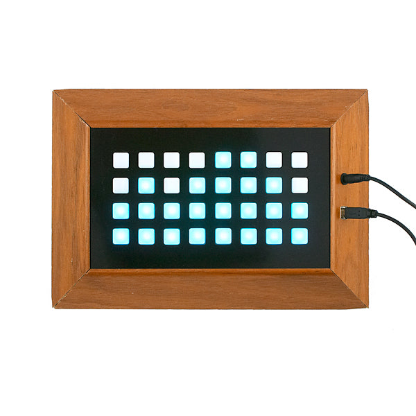
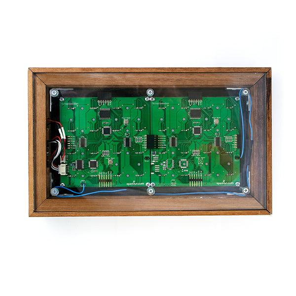
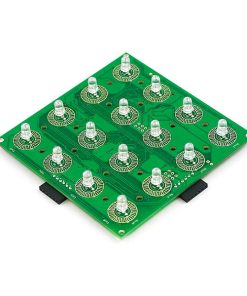
The Button Pad Controller SPI was designed to compliment the Button Pad Controller USB; though it can also be used as a standalone device. The board is 4”x4” and has 16 tri-color LEDs and 16 corresponding button pads (i.e. The button pad surrounds the LED). The boards communicate via an SPI bus, and up to 10 Button Pad Controllers can be connected in a system (including one Button Pad Controller USB). The default firmware uses a 9 bit color scheme. Each board comes configured to work as a standalone unit and must be reconfigured for multiple board systems.
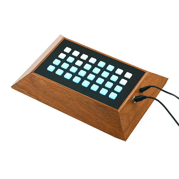
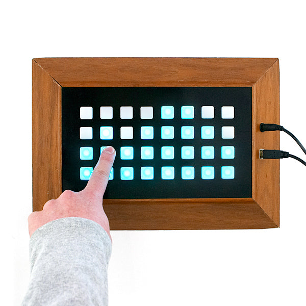
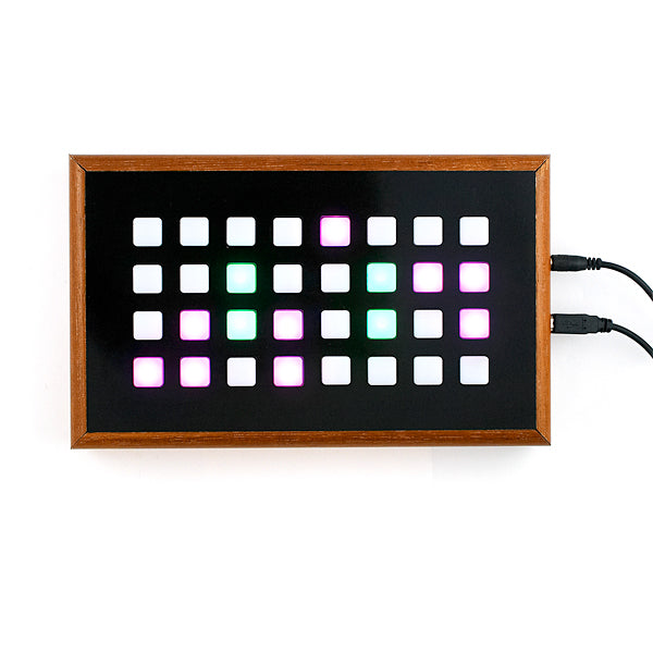
We do not sell the frames shown in the photograph. We put those together for our own use as a demonstration of what two units look like, boxed up together.
Unit comes fully assembled and tested as shown. Unit does not include top button pad (listed below).
Note: We’re using new RGB LEDs which have the blue and green pins swapped. When setting the LED color, you’ll need to swap the blue and green values in the command structure. Visually, nothing on the board has changed.
Note: Although the hardware is technically capable of 24-bit color, the firmware limits the board to 9-bit color. Check the comments below for the reasoning.
Documents:
- ButtonPadControllerSPI_v15.c (Zip)
- Eagle Files
- Schematic
- User Guide
Professional packing and fast shipping
Our long-standing partnership with UPS FedEx DHL and other global carriers gives us the ability to provide a range of shipping services. Our warehouse staff is highly educated and will package the items according to the exact and precise specifications. Before shipment, all items are thoroughly inspected and secured. We ship to thousands clients every day from all over the world. The fact that we are dedicated to becoming the largest online retailer in the world is clear. We have distribution centers as well as warehouses located in Europe and the USA.
Note: Orders that contain multiple items will have a different processing time for each item.
Prior to shipment, we inspect the ordered items thoroughly. The majority of orders are shipped within 48 hrs. The delivery time should be between 3-7 working days.
Returns
The stock is dynamic and we do not completely manage it because many stakeholders are involved, including our warehouse and factory. Stocks are subject to change at any time. Be aware that it is possible that your order will be out of stock after you have placed the order.
Our policy is valid for a period of 30 days. We are unable to exchange or refund your order when it's been 30 days since you purchased it.
You can only return a product in the event that it is not used and still in the same condition when you first received it. You must have the item in the original packaging.
